
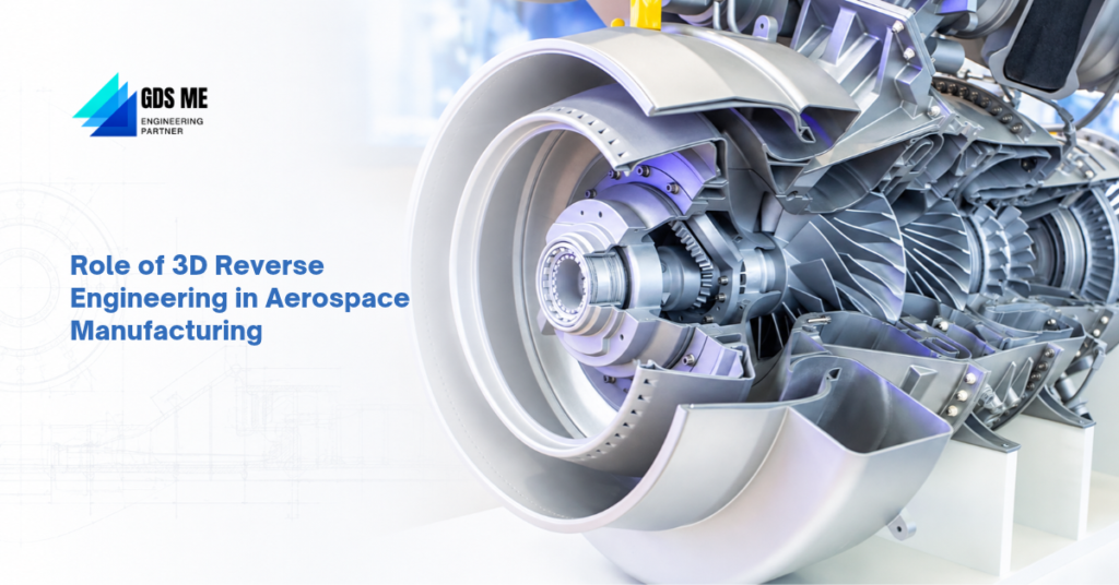
Imagine your company needs to reproduce an aircraft component, but the original CAD file is nowhere to be found. Maybe the manufacturer has stopped making it. Or the drawings you have are old and don’t quite match the actual part anymore.
This can be a real problem when working with older aircraft components. Some parts have complicated curves, tiny features and very specific dimensions. You can’t simply measure a few points and start making a replacement. The component has to fit properly, work with the other parts and meet the required performance standards.
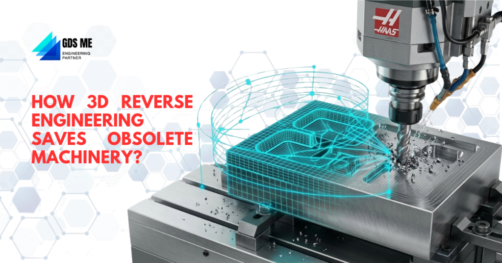
3D reverse engineering is the right solution here. Engineers can scan the existing component, capture its geometry and use the scan data to rebuild a digital CAD model. It can be particularly useful for legacy components, modified parts and shapes that are difficult to measure manually. R&D teams can also use it to study an existing design before making changes. And for MRO organizations, it can help when an original replacement part is no longer available.
For aerospace manufacturers, component suppliers and MRO teams, this gives them another option when original design information is missing or outdated.
GDS Middle East (GDSME) offers Geomagic 3D reverse engineering solutions for engineering businesses. Let’s look at how this technology can be used in aerospace manufacturing.
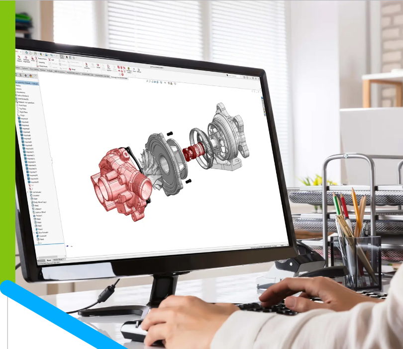
Credit – https://hexagon.com/products/geomagic-for-solidworks
Understanding 3D Reverse Engineering in Aerospace
As the name implies, the process begins with the physical component. A 3D scanner captures its surface geometry and collects thousands or even millions of measurement points. This creates a point cloud, which later, after processing, becomes a polygon mesh.
The scan is not the finished CAD model.
The data needs cleaning, alignment, and processing. Engineers then identify the important features and use 3D reverse engineering software to reconstruct the geometry.
Take an aircraft bracket. You have the physical part but no original CAD file. A scan can capture its mounting holes, curves, and other features. Engineers can then rebuild the design in CAD and use it for further work.
The scan gives you a digital representation of the physical part. The reconstructed CAD model gives you an editable file. That is an important difference.
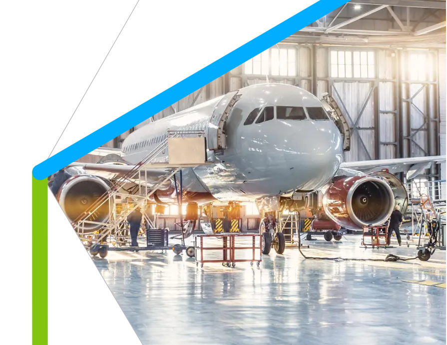
Credit – https://hexagon.com/industries/aerospace
Challenges in Recreating Complex Aerospace Components
Some components are fairly straightforward to measure. Others are a different story.
- Tight tolerances are one concern. A small difference in a mounting hole or mating surface can affect how a component fits into an assembly. Engineers need reliable measurement data, not just an approximate shape.
- Then there are complex surfaces. Turbine blades, engine housings, and ducts have curves, changing profiles, and areas that are difficult to reach with conventional tools.
- Missing drawings make things harder, particularly with older aircraft parts. Even when a drawing exists, it may not show the component’s present condition.
- Surface conditions matter as well. Aerospace parts may be made from titanium, aluminum alloys, or nickel-based superalloys. Coatings, reflective finishes, wear, and damage can all affect scanning.
- And there is the time factor. MRO teams often work around maintenance schedules. Waiting for old design files or replacement parts isn’t always practical.
When a physical sample is available, 3D scanning helps engineers develop a digital reference for further work.
How 3D Scanning Fits into Aerospace Reverse Engineering
There are several points in an aerospace project where scan data can come in handy. A few examples:
- Checking the assembly (how parts fit together): A bracket may look fine on its own, but does it line up with the mounting points in the assembly? Engineers can use scan data to look at these details before making changes.
- Working with difficult shapes: Turbine blades, curved housings and other irregular components aren’t always easy to measure. Scanning helps capture these details without relying on a long list of manual measurements.
- Making design changes: Sometimes the idea isn’t to reproduce the original part exactly. Engineers may want to study its existing design and work on a modified version. The scanned model gives them something to start with.
- Keeping teams on the same page: Design, production and inspection teams may all need access to the component data. Having a shared digital reference can make this easier, especially on projects involving teams in different locations.
The quality of the final model also depends on what happens after scanning. The data needs to be processed and worked on using suitable reverse engineering software. This is one reason some aerospace businesses prefer specialist support rather than managing the entire process in-house.
Aerospace Components That Can Benefit
Where can manufacturers use this process? Quite a few places, actually.
- Turbine blades and engine components: The curved profiles and detailed surfaces of turbine blades and engine components are often difficult to measure manually. 3D scanning can capture these details for component reconstruction and dimensional analysis.
- Aircraft brackets and structural components: Mounting holes, slots, and connection points when original drawings are unavailable.
- Ducts, manifolds and housings: Their changing cross-sections and curved passages make manual measurement difficult.
- Landing gear components: Suitable housings, brackets, and mechanical fittings can be scanned to recover geometry and support inspection.
- Legacy aircraft parts: When a discontinued component is still available physically, engineers can use it to recreate a digital reference.
Of course, a reconstructed model doesn’t automatically mean a component is ready for aircraft use. The necessary engineering checks and approvals still apply.
Benefits of 3D Reverse Engineering for Aerospace Manufacturers
One of the first things manufacturers may notice is reduced dependence on manual measurements. Scanning captures extensive surface data in a single process, which can save time when working with complex parts.
There are other benefits worth considering.
- Better access to geometry: Engineers can examine the actual physical shape rather than relying entirely on older drawings.
- Less dependence on legacy files: Missing CAD data doesn’t necessarily stop the reconstruction process if a physical sample is available.
- Support for design work: R&D teams can use reconstructed models to study existing components and explore modifications.
- Digital records: Scan data and CAD models can be saved for future reference.
- Maintenance support: MRO teams can use digital geometry for component assessment and reproduction planning.
It won’t replace inspection or engineering validation. But having detailed digital data makes several stages of the work easier.
GDS Middle East and Geomagic Solutions
If you’re planning to use 3D reverse engineering in your aerospace work, there’s more to consider than just the software. You’ll need a suitable scanner too. And depending on your team’s experience, you may need help with setup, training and technical support along the way.
GDS Middle East (GDSME) works with engineering and manufacturing businesses across the UAE, Saudi Arabia, Qatar, Oman and the wider GCC. The company offers Geomagic software and Creaform 3D scanners, covering both sides of the scan-to-CAD process.
You may be looking at Design X for reverse engineering, Control X for inspection, or trying to find a Creaform scanner that suits your work. The GDSME team can help you go through the available options.
Why Choose GDSME?
Choosing software is one thing. Making sure it fits your team’s work and existing engineering setup is just as important.
- Help choosing the right product: Not sure whether Design X or Control X is the better fit? You can discuss what your team needs to do and look at the options with GDSME.
- Scanner and software under one roof: GDSME also offers Creaform 3D scanners. So you can discuss the scanner and software requirements together, rather than treating them as two separate purchases.
- Training and technical support: Getting the right training in the software enables you to work efficiently from the first day. GDSME helps with implementation and training, and your team can reach out for technical support when needed.
- GCC presence: GDSME works with businesses in the UAE, Saudi Arabia, Qatar, Oman and across the wider GCC.
FAQs
A. Depends on the product and licence. If you’re considering Design X or Control X, check with GDSME for pricing based on your requirements.
A. Maybe not. If you already have a scanner, ask whether its scan data can be used with Geomagic before planning a new purchase.
A. Yes, training and technical support are available through GDSME. You can ask about this along with the software purchase.
A. Design X is for reverse engineering; Control X is for inspection. If you’re still unsure which one you need, explain your application to the GDSME team.
Missing CAD files, older components and difficult geometries are all challenges aerospace manufacturers may come across. 3D scanning and reverse engineering can help when the original design information isn’t available or needs to be recreated.
Of course, the scanner and software need to suit the work you’re doing. If you’re considering Geomagic or Creaform solutions in the UAE, Saudi Arabia or elsewhere in the GCC, GDS Middle East can help you explore the available options.